Mozzi output modes - from simple to HIFI
When Mozzi came to life around 2012 the world was simple: Only one CPU family was supported, and only a single output mode. That quickly grew to several different output options, and today Mozzi runs on a wide variety of different MCUs with very different hardware capabilities.
The table at the bottom of the page provides an overview what modes are supported on which board, and importantly, what pin(s) to expect audio output on. This may look quite confusing on first glance, but actually, in a default configuration, output is always sent to a single pin in the form of a direct (emulated) analog signal. We’ll look at that scenario first, and it is also very much recommended to stick to the default mode, at first.
Single pin output modes
Here, “single pin” means one output pin per audio channel, so it could also be two pins for stereo output.
Output using a true hardware DAC
Things are easy, if your MCU comes with a true hardware DAC, which outputs a true analog signal. This corresponds to the “DAC” column in the table
below, and the configuration option MOZZI_OUTPUT_INTERNAL_DAC.
Boards that fall into this category include Teensy 3.1, Arduino Giga, and ESP32. Note however, that for the last one, the output resolution is only 8 bits.
When using this modes, all you need to worry about is whether the output is capable of providing enough output current. I.e. you may need to follow up with a generic amplifier circuit to drive low impedance speakers, but that’s it.
Modulated output (PWM or PDM)
Most boards do not feature a hardware DAC, however. In this case, an analog signal needs to be emulated by quickly toggling a digital pin high or low.
This can either happen using so-called pulse width modulation (MOZZI_OUTPUT_PWM) or pulse density modulation (MOZZI_OUTPUT_PDM_VIA_I2S or (MOZZI_OUTPUT_PDM_VIA_SERIAL). We’re not going into detail, here, but it should be noted that in both cases there is a trade-off between the
granularity of the output voltages (i.e. how may different voltage levels can be emulated between logical high and logical low, and the speed at which
these values can be emulated (the carrier frequency).
Simply put, using pulse width modulation (PWM), if you want 12 bits of output resolution, i.e. 4096 distinct signal levels, a digital output
pin will have to be held high (or low) for up to that many CPU cycles, so this will generally require a clock on the order of at least 100 Mhz
in oder to push the carrier frequency outside the audible range. See configuration options MOZZI_PWM_RATE, and MOZZI_AUDIO_BITS,
or MOZZI_PDM_RESOLUTION if you want to tweak this tradeoff.
In some configurations, you (or your kids/pets, how can perceive high frequencies much better), may notice a high-pitch noise, at the carrier frequency. Using a higher carrier frequency - if possible - may mitigate this to some degree. See the API documentation for details on what you can tweak. However, for best quality it will often make sense to add a low-pass filter, which may be as easy as adding a capacitor and a resistor. See the output circuits page for details.
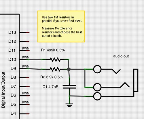
Output circuit for 2-pin-PWM (“HIFI”) mode
Mozzi’s MOZZI_OUTPUT_2PIN_PWM (formerly known as “HIFI”) audio mode combines the output of 2 pins in a technique called dual PWM, which is explained in detail at Open Music Labs.
This output mode needs a different and more complex output circuitry than the single pin modes, and using the regular single pin circuit for “HIFI” will result in terribly distorted sound. In case of difficulties (but also in general), it is very much recommended to try the default output mode, first, and switch to any other mode only once you’ve verified that works. Don’t go straight for “HIFI” just because is sounds promising.
Here’s the circuit for Mozzi, based on the Open Music Labs article.
Not all boards support the 2-pin PWM mode, but some are capable of quite good output resolution in their default mode.
Low-pass filtering
The dual PWM mode, too, can profit from a hardware filter attenuating the carrier frequency. In 2-pin PWM mode, the filter would be applied on the combined audio output signal rather than straight from pin 9 in single pin mode.
Advantages of HIFI mode
- Higher resolution sound than single pin PWM modes.
- Generally doesn’t need a notch filter on the audio signal because the carrier frequency is out of hearing range.
Disadvantages
- Requires 2 pins, 2 resistors and a capacitor, so it’s not so quick to set up compared to a rough, direct single-pin output in default mode.
Download
Download a Fritzing file with breadboard, schematic and circuit board layouts here.
Output to external DACs (or custom circuitry)
Native (I2S) DAC interface
On a few platforms (including ESP8266 and ESP32), Mozzi has inbuilt support for interfacing with certain DAC ICs using the I2S interface. This interface uses (usually) three pins to transmit audio samples in a digital format:
- a bit clock line, usually labelled SCK or BCLK
- a word clock line, usually labelled WS or LRCLK
- a data line, often labelled SD, SDATA, SDIN, SDOUT, DACDAT, or similar
- (some variants may include additional pins, but these do not seem common on MCUs, at the time of this writing)
The pins used for these lines may or may not be configurable, depending on your hardware. See the API documentation for details.
Unfortunately, the I2S format comes in several variants, and feeding a DAC data in the wrong format will lead to terribly distorted sound. Again, refer to the API documentation for configuration options, and/or make sure to use a DAC chip that is known to be supported.
Custom interface to external DACs or other hardware
On all platforms, you can provide custom output routines, which allow you to output to anything from hand-made resistor ladders over purchased dedicated DAC ICs to
a bluetooth audio sink. To enable this, take a look at the configuration options MOZZI_OUTPUT_EXTERNAL_TIMED and MOZZI_OUTPUT_EXTERNAL_CUSTOM (see API documentation).
Mozzi also ships with a whole section of examples for connecting to external components, including MCP4922 and PT8211 DACs (File->Examples->Mozzi->13.External_Audio_Output).
The basic procedure for using the two external output modes is this:
// before including Mozzi.h, configure external audio output mode:
#include "MozziConfigValues.h"                        // for named option values
#define MOZZI_AUDIO_MODE MOZZI_OUTPUT_EXTERNAL_TIMED  // configure external mode
#include <Mozzi.h>

// [most of your sketch is as usual]

// additionally provide this function.
void audioOutput(const AudioOutput f) {
  // put here code to output the sample encapsulated by the structure f:
  // This holds either one (mono) or two (stereo) channels, which can be
  // obtained using f.l() and f.r().
  // Each contains a zero-centered integer value scaled to MOZZI_AUDIO_BITS resolution

  // e.g.:
  myDAC.write(f.l() + MOZZI_AUDIO_BIAS, f.r() + MOZZI_AUDIO_BIAS);
}
The audioOutput() function in the above example will now be called at MOZZI_AUDIO_RATE. In some cases, however, it will be preferrable to delegate the rate
control elsewhere. For instance, maybe you have a library that will feed an external DAC via a hardware DMA mechanism. For such a case set the output mode to
MOZZI_OUTPUT_EXTERNAL_CUSTOM and provide an additional function canBufferAudioOutput() which should return true whenever another sample should be generated:
#include "MozziConfigValues.h"
#define MOZZI_AUDIO_MODE MOZZI_OUTPUT_EXTERNAL_CUSTOM
#include <Mozzi.h>

void audioOutput(const AudioOutput f) {
  // e.g.:
  myDAC.write(f.l() + MOZZI_AUDIO_BIAS, f.r() + MOZZI_AUDIO_BIAS);
}

bool canBufferAudioOutput() {
  return (!myDAC.bufferFull());
}
Matrix of supported platforms and output modes
Supported boards, output modes and default pins
Table is not necessarily complete. Abbreviations explained below the table. The default output mode is framed with a border in each row. If stereo is supported, in a mode, the cell has a red/blue background, and (where applicable) the second pin number is given in parentheses (+X). Check the hardware section of the API-documentation for platform specific notes and (pin) configuration options.
| Board or family / Output mode | PWM-1 | PWM-2 | PDM | inbuilt DAC | I2S DAC (native) |
| ATmega328/168: Uno (R3), Nano, Pro Mini, Duemilanove, Leonardo, etc. | 9 (+10) | 9, 10 | - | - | - |
| ATmega32U4: Teensy, Teensy2, 2++ B5/B6 correspond to pins 14/15 in Arduino | B5 (+B6) | B5, B6 | - | - | - |
| ATmega2560: Arduino Mega, Freetronics EtherMega, etc. | 11 (+12) | 11, 12 | - | - | - |
| ATmega1284: Sanguino | 13 (+12) | 13, 12 | - | - | - |
| Teensy3.x - note: DAC Pin number depends on model: A14, A12, or A21 | - | - | - | DAC | - |
| Teensy4.x | A8 (+A9) | - | - | - | - |
| LGT8F328P: "Register clone" of the ATmega328, uses the same code in Mozzi | 9 (+10) | 9, 10 | - | - | - |
| SAMD: Arduino Nano 33 Iot, Adafruit Playground Express, Gemma M0 etc. | - | - | - | A0/speaker | - |
| Renesas Arduino Core: Arduino Uno R4 | - | - | - | A0 | - |
| Arduino MBED Core: Arduino Giga (only model tested so far in this family) | - | - | SERIAL2TX | A13 (+A12) | - |
| STM32 maple core: Various STM32F1 and STM32F4 boards, "Blue/Black Pill" | PB8 (+PB9) | PB8, PB9 | - | - | - |
| STM32duino (STM official) core: Huge range of STM32Fx boards | PA8 (+PA8) | PA8, PA9 | - | - | - |
| ESP8266: ESP-01, Wemos D1 mini, etc. note: Beware of erratic pin labels | - | - | GPIO2 | - | yes |
| ESP32: that has an internal DAC (only ESP32) note: Beware of vastly different pin labels across board variants | 15 (+16) | yes | GPIO25 (+GPIO26) | yes | |
| ESP32-S/C/H/P: that do not have an internal DAC note: Beware of vastly different pin labels across board variants | 15 (+16) | yes | yes | ||
| RP2040: Raspberry Pi Pico and friends | 0 (+1) | 0, 1 | - | - | yes |
| CH32: WCH CH32X035 (RISC-V) | PA6 | PA6, PA7 | - | - | - |
- PWM-1: 1-pin PWM mode (
MOZZI_OUTPUT_PWM) - PWM-2: 2-pin PWM mode (
MOZZI_OUTPUT_2PIN_PWM) - PDM: Pulse density modulation, may be either
MOZZI_OUTPUT_PDM_VIA_SERIALorMOZZI_OUTPUT_PDM_VIA_I2S - inbuilt DAC:
MOZZI_OUTPUT_INTERNAL_DAC - I2S DAC (native): native support for externally connected I2S DACs (
MOZZI_OUTPUT_I2S_DAC). Since this requires several, often configurable pins, and is never the default option, no pin numbers are shown in this table. - All platforms also support “external” output modes (
MOZZI_OUTPUT_EXTERNAL_TIMEDorMOZZI_OUTPUT_EXTERNAL_CUSTOM), which allow for connecting DACs or other external circuitry. </span>