The interface between Mozzi and the Arduino environment consists of four main functions. These are startMozzi(), updateAudio(), updateControl() and audioHook(), visible in the “User space” section in the figure below. All four are required for a Mozzi sketch to compile.
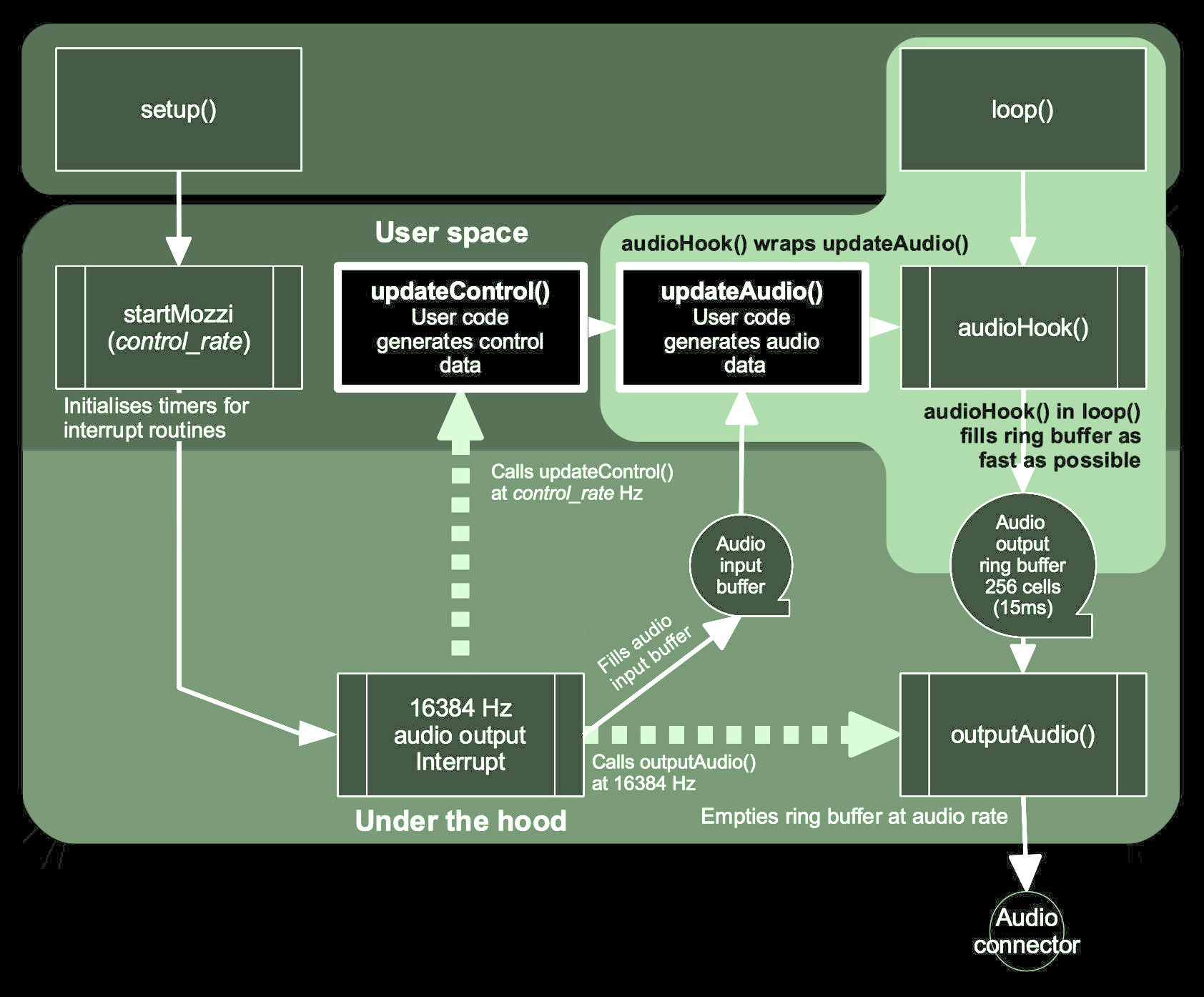
Internal details differ in some implementations, but the above schematic, prepared for early Mozzi versions, is still accurate where it comes to the interaction of the four user space functions, and hopefully gives a basic idea.
startMozzi() goes in Arduino’s setup(). It starts a timer which regularly sends audio out from the audio output buffer, and calls updateControl() at the configured MOZZI_CONTROL_RATE in Hz (defaulting to 64 Hz).
updateControl() is where any analog or digital input sensing code should be placed and relatively slow changes such as LFO’s or frequency changes can be performed.
updateAudio() is where audio synthesis code should be placed. This runs on average at MOZZI_AUDIO_RATE, i.e. typically 16384 times per second or even twice as much, so code here needs to be lean. The only other strict requirement is that it needs to return zero-centered samples in the required bit range. The functions MonoOutput::from8Bit(), MonoOutput::from16Bit(), and MonoOutput::fromNBit() (or their StereoOuput-counterparts) help in scaling the result of your computations to the required output range, portably, and efficiently.
audioHook() goes in Arduino’s loop(). It wraps updateAudio() and takes care of filling the output buffer, hiding the details of buffering and actual output on hardware from user space.
In most implementations Mozzi uses hardware interrupts / timers on the processor which automatically call
interrupt service routines (ISR) at regular intervals. startMozzi() sets
up an interrupt for audio output at a sample rate of MOZZI_AUDIO_RATE (16384 Hz on AVR or 32768 Hz elsewhere, by default). A counter in the audio output routine is used to call updateControl.
On the AVR (ATmega) architecture, the 16 bit Timer 1 is claimed by Mozzi on the ATmega processors for audio and control. 2-pin PWM (“HIFI”) mode additionally employs Timer 2 with Timer 1 for audio.
The output buffer has 256 cells which equates to a maximum latency of about 15 milliseconds at 16384 Hz (half as much at 32768 Hz), to give leeway for control operations without interrupting audio output. The buffer is emptied behind the scenes by the regular 16384 Hz / 32768 Hz audio interrupt.